Quick Links
Timing Devices
In Satellite Laser Ranging (SLR) there are two timing approaches used: the interval counter and the event timer. Time interval units measure the time of flight (TOR) of the optical pulse, while event timers compute this value by differencing the laser fire epoch and the satellite echo epoch.
Below are two tables listing timers used for SLR in the past and presently.
Interval Timers
| Year | Manufacturer | Model | Resolution (ps) | Jitter (Ps) | Linearity (Ps) | Stability [Ps/K] | Stability [Ps/hour] | Max. repetition rate (Hz) | Max. TOF |
|---|---|---|---|---|---|---|---|---|---|
| 1988 | Stanford Research Systems | SR620 | 4 | 25 | 50 | - | - | 100 | 1000 s |
| 1982 | Hewlett-Packard | 5370B * | 20 | 35 | 20 | - | - | 10 | 10 s |
| 2002 | Inst. Electronics and Computer Science, Riga, Latvia | A013a * | 10 | 20 | 2 | - | 2 | 80 | 0.209 s |
Event Timers
| Year | Manufacturer | Model | Resolution (ps) | Jitter (Ps) | Linearity (Ps) | Stability [Ps/K] | Stability [Ps/hour] | Max. repetition rate (Hz) |
|---|---|---|---|---|---|---|---|---|
| <1980 | Ortec | TD811 | 100 | 40 | ||||
| 1999 | PESO Cons. | PET4/TIGO | 1.2 | 3.5 | 3 | <0.3 | <0.5 | >100 |
| 2006 | P_PET-C | 1.2 | 3 | - | <1 | <1 | 2000 | |
| 1998 | EOS | MRCS V.4 | 2 | 10 | 1 | - | 1 | 1000 |
| 1998 | HTSI | MLRO | 0.5 | <2 | - | - | 0.5 | 2000 |
| 2003 | Inst. Electronics and Computer Science, Riga, Latvia | A031-ET * | 1 | 10.8 | <1 | 0.1 | 0.5 | 1000 |
| 2005 | Eventech, Riga, Latvia | A032-ET | 1 | 7-8 | <1 | 0.5 | N/A | 10 |
| 2011 | Eventech, Riga, Latvia | A033-ET | 1 | 2.2 | <1 | 0.1 | N/A | 1,000,000 |
| 2023 | Eventech, Riga, Latvia | ESTT- 7 Series | 1 | 1 | <1 | <0.1 | N/A | 25,000,000 |
NOTES: HP spun-off its test, measurement and monitoring device business into Agilent Technologies. HTSI was formerly Allied Signal Technical Services (ATSC)
* Denotes past model no longer manufactured.
Best Practice when using your TOF device
Below are the BEST practices that are general and applicable to any time of flight device (time interval count or event timer) used for SLR/LLR applications:
1. Signal integrity:
- Use only high-quality cables and connectors.
- Take great care with shielding and grounding (earthing) in order to make sure that all noise sources are minimized.
2. External frequency ("Clock source"):
- Supply each timer with a separate, high quality 5 or 10 MHz sine wave.
- Make sure that the timer is set up to take an external "clock source".
3. Power supply:
- Never switch off. If the timer has been switched off for any reason, allow adequate warm up before any operational use. Please refer to the manufacturer's operations manual for more information.
- Use a stable mains voltage supply (for this and many other instruments it is useful to monitor the mains voltage regularly and warn when it falls).
- Use a transient suppressor to prevent voltage "spikes" reaching the timer.
4. Environmental Control:
- Maintain a stable working environment around the timer.
- Keeping the temperature constant is particularly important.
- Monitoring the temperatures of air at the timer air inlet and air outlet will give quick feedback of potential problems;
- Maintain a good airflow around and through the instrument.
- Be aware that nearby air-conditioning units, cycling on and off, can substantially alter the temperature of the air in the vicinity of the timer, even in a supposedly temperature stabilized room.
5. Non-linearity/timer calibration:
- For picosecond event timers, perform optical calibration as recommended by the manufacturer.
- For time interval counters, either cluster the time interval units to help "average" non-linearities or calibrate each device versus a picosecond event timer and model any errors in data processing.
6. Jitter:
- Monitor the jitter of the timer at least monthly.
TOF Devices:
HP5370B
The HP5370B is a time interval and frequency counter, capable of measuring time intervals as small as 20 picoseconds. Time intervals up to ±10 seconds can be measured with 20 ps relative accuracy, and 65 Ps absolute accuracy, assuming a 'stable' external timebase (frequency) is used. A rear-panel input lets you connect any external 5 MHz or 10 MHz source as a timebase. Statistics are automatically calculated and reported on samples as large as 100,000, including: sample mean, maximum, minimum, and standard deviation. Standard GPIB interfaces control all front panel functions, and printers can be directly connected to the HP5370B.
Its ease of use, relativity low cost, and its relativity good linearity and absolute accuracy characteristics are the primary reasons, many ILRS stations use the HP5370B as their primary range-measuring instrument, and other stations have access to them. The prime drawback of the HP5370B is no longer made and Agilent Technologies (formerly HP) discontinued its support, however; refurbished units can still be purchased. Another drawback for SLR applications is its maximum laser repetition rate of 10Hz.
Picosecond Event Timer (PET)
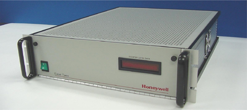
The PicoSecond Event Timer (PET) is a epoch event counter, capable of measuring time intervals to 1.2 picoseconds (ps). There is no limit on the time interval to be measured with 2.5 ps relative accuracy, and few ps absolute accuracy. Four Thales, formerly Dassault Electronique, timing modules are used in the PET. One vernier is used for the start (i.e. laser fire) and three verniers are used for the 3 independent detectors. For laser ranging applications, an external timebase (frequency) should be used to maximum SLR data accuracy. A panel input lets you connect any external 10 MHz source as a timebase. Standard RS-232 interfaces control all front panel functions. The PET can act as a stand alone timer or can be optionally used in parallel with an existing SLR timing system in Portable Calibration Standard Configuration.
Its ease of use and picosecond jitter and picosecond absolute accuracy are the key benefits and the reason a few ILRS stations use the PET as their primary range-measuring instrument.
HTSI MLRO Event Timer

The HTSI MLRO Event Timer (ET) is capable of measuring time intervals to 0.5 picoseconds (ps) with an RMS jitter of less than 2 Ps For laser ranging applications, an external timebase (frequency) should be used to maximum SLR data accuracy. A panel input lets you connect any external 10 MHz source as a timebase. The ET can be used to measure up to 512 events at a 10 megahertz rate before being read by computer and is able to work at KHz data rates. The ET can continuously monitor up to 12 inputs, identifying which input provided the signal that was time-tagged. A report on the HTSI Event Timer System was made to the 15th ILRS Workshop in 2006.
SR620
Written by R. Wood, P. Gibbs, D. Walters and C. Potter (Herstmonceux), 15 November 2002, edited by Van Husson (ILRS Central Bureau)

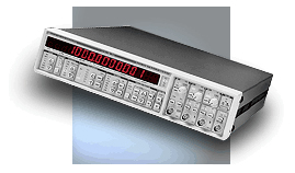
The SR620 is a time interval and frequency counter, capable of measuring time intervals as small as 25 picoseconds. Time intervals up to ±1000 seconds can be measured with 50 ps relative accuracy, and 500 ps absolute accuracy. For laser ranging applications, an external timebase (frequency) should be used to maximum SLR data accuracy. A rear-panel input lets you connect any external 5 MHz or 10 MHz source as a timebase. Statistics are automatically calculated and reported on samples as large as 1 million, including: sample mean, maximum, minimum, and standard deviation or Allan variance. Standard GPIB and RS-232 interfaces control all front panel functions, and printers or plotters can be directly connected to the SR620. (SR620 Operating Manual And Programming Reference Handbook)
Its ease of use, low cost, and long-term stability are the primary reasons, many ILRS stations use the SR620 as their primary range-measuring instrument, and other stations have access to them. The prime drawback of the SR620 for SLR application is its large non-linearities as a function of time interval (i.e. range) and its 500 ps absolute accuracy, but these errors are stable over the long term and if measured against a known standard then can be removed in data processing.
Best Practices for the SR620:
The following paragraphs offer some collected wisdom and should help SR620 users to get the best possible performance from their instrument - much is just common sense, but it is hoped that some material will allow users to get better results from their instruments.
1. Power supply:
- The best policy is "never switch off".
- Use a stable mains voltage supply (for this and many other instruments it is useful to monitor the mains voltage regularly and warn when it falls).
- Use a transient suppressor to prevent voltage "spikes" reaching the timer.
2. Switching on:
- If the timer has been switched off for any reason, allow at least one hour for it to warm up before any operational use.
3. Environmental Control:
- Maintain a stable working environment around the timer.
- Keeping the temperature constant is particularly important.
- Monitoring the temperatures of air at the timer air inlet and air outlet will give quick feedback of potential problems;
- Maintain a good airflow around and through the instrument.
- Be aware that nearby air-conditioning units, cycling on and off, can substantially alter the temperature of the air in the vicinity of the timer, even in a supposedly temperature stabilized room.
4. Signal integrity:
- Use only high-quality cables and connectors.
- Take great care with shielding and grounding (earthing) in order to make sure that all noise sources are minimized.
5. External frequency ("Clock source"):
- Supply each timer with a separate, high quality 10 MHz sine wave
- Make sure that the timer is set up to take an external "clock source":
- On the front panel, select the Calibration menu ("cAL");
- Set "cLoc SourcE rear";
- Specify the frequency by "cLoc Fr 10000000".
- Keep it permanently connected to the timer;
- Make sure that the input is properly terminated with a 50 Ohm impedance via a standard BNC T-connector (since timer inputs are >1 kilo-ohm).
6. Multiple timers:
- If you use more than one timer, try to use identical cable lengths to feed:
- All start channels;
- All stop channels;
- All external frequency inputs (UR43 co-ax).
- This arrangement is recommended in order to minimize any possible phase effects.
7. Timer calibration:
- The manual says that the timer "has a sophisticated, built-in, auto-calibration routine that nulls insertion delays between start and stop channels, and compensates for the differential non-linearities inherent in analogue time-measurement circuitry. The auto-calibration routine takes about two minutes to perform and should be run every 1000 hours of operation." It is therefore recommended that users regularly (every 8 weeks or so) perform an Autocal (handbook, version 2.2, page 68) to optimize timer performance.
- Regularly (annually) optimize the amplitude of the internal 90 MHz counting frequency of the timer (see handbook, version 2.2, page 69).
8. Jitter:
- Monitor the jitter of the timer at least monthly.
- A simple experiment to do this consists of splitting a single pulse (generated from detector noise or a pulse generator) and feeding one pulse directly into the start channel and the other via a long cable into the stop channel. Many hundreds, or even thousands, of measurements of the time differences between the two will show a jitter dependent only on the performance of the timer. Typical results are about 25-30ps.
9. Non-linearity:
- If you have more than one timer regularly, monitor the range dependence of time interval measurements.
- A simple experiment to do this would be to inter-compare the timer readings, shot by shot, as a function of satellite range. Examine the data for many passes and all satellites to display any range dependence of the timers.
- As an independent check data may be collected over the full range of satellite ranges by exposing the detector to (reduced) daylight and successively gating at different ranges using a time delay generator.
10. Level settings:
- It has been found that setting the discriminator levels for input pulses using the hand controls on the front panel does not give consistent or reproducible values for these settings;
- Best results are obtained by using the hand controls to set values far different from (preferably with the opposite sign) those required for the inputs actually to be used, and then setting the required values from software;
- This approach has three advantages:
- Superior, long-term consistency of setting;
- Simple visual inspection of the front panel immediately reveals any setting failures;
- If the software fails to set the thresholds, the timers will not collect any (erroneous) data.
11. Record keeping:
- Since the characteristics (e.g. range dependencies) of each SR620 are different, label/number each SR620 distinctly.
- Document each time your SR620 is swapped with another SR620 or when your data processing system has been modified to model the SR620 non-linearities.


